MMT 432/28 S Transverter.
2020 update.
This is the way I used to get onto 70cms. from my shack. It is old, and serves me well, like my TS700. I drive it with a TS50 which is roughly half its age, but also getting to be a bit long 'in the tooth'.

(Right click the image for a much larger view.)
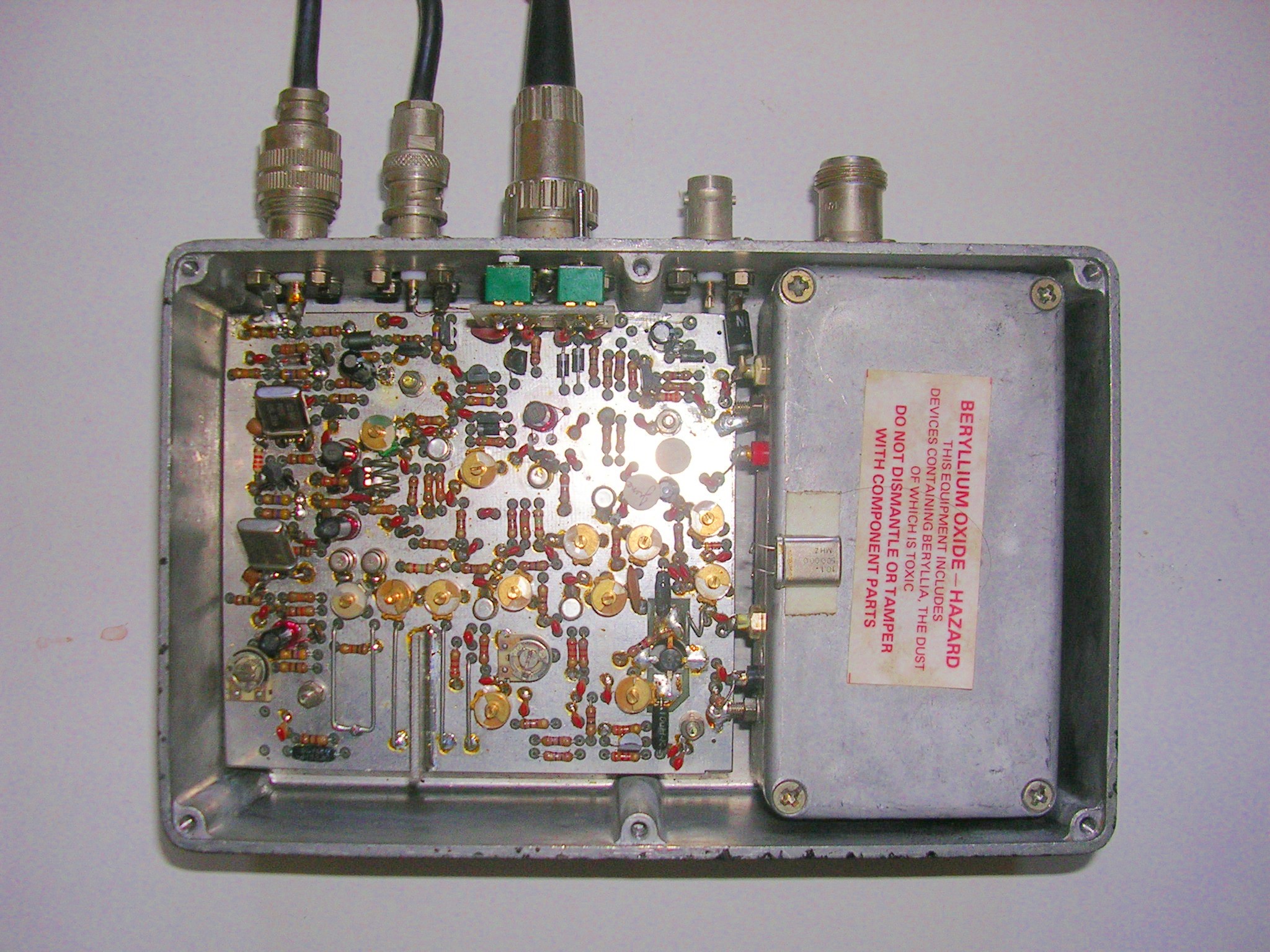
In the early days of UHF and satellites this unit was intended to give HF operators access the UHF dx. The 'S' in the model number is for 'Satellite' and refers to the option of moving the coverage up 2MHz, from 432-434 mHz to 434-436 mHz. (The intended drive frequency range is 28-30mHz.) Two switches, green at the top of the image, are 'Hi or Lo' for Rx and Tx.
With separate Rx and Tx range switches I used to work 70cms repeaters (+1.6mHz split) by enabling 2mHz 'up' on Tx, but splitting to Tx at -400kHz on the TS50. I no longer need this split so I have changed the 2MHz up crystal to one which gives 7.6MHz up. It cost more than a budget radio! This makes setting up the TS50 easier, but I still need split frequency operation in order to activate the CTCSS tone so both A and B frequencies are the same. (The original crystal is stuck to the PA box just in case I ever need it. If you email me the frequency of my new one (its not readable) you will get a special mention on this page! (I won't let on if you get it wrong!) I can now flick the Rx switch to 'Hi' and listen on the input.
The crystal is trimmed with an inductor and I had difficulty in getting it to work reliably at the right frequency. I have just fitted a 10pf cap. in series with it. 'Sweet as a nut' now! I must have done the same for the standard crystal after I first got the transverter as well.
After carefully trimming the crystal and making other adjustments to optimise my audio quality a mysterious musical 'hum' rather like fan noise was reported. I could not hear it on my transmission. It was an artifact of the repeater function. The cause was too high a level of the CTCSS tone. All is well now that I have turned it down (in the TS50). It became too high after I turned up the deviation level, not expecting it to affect the CTCSS level as well.

(Right click the image for a much larger view.)
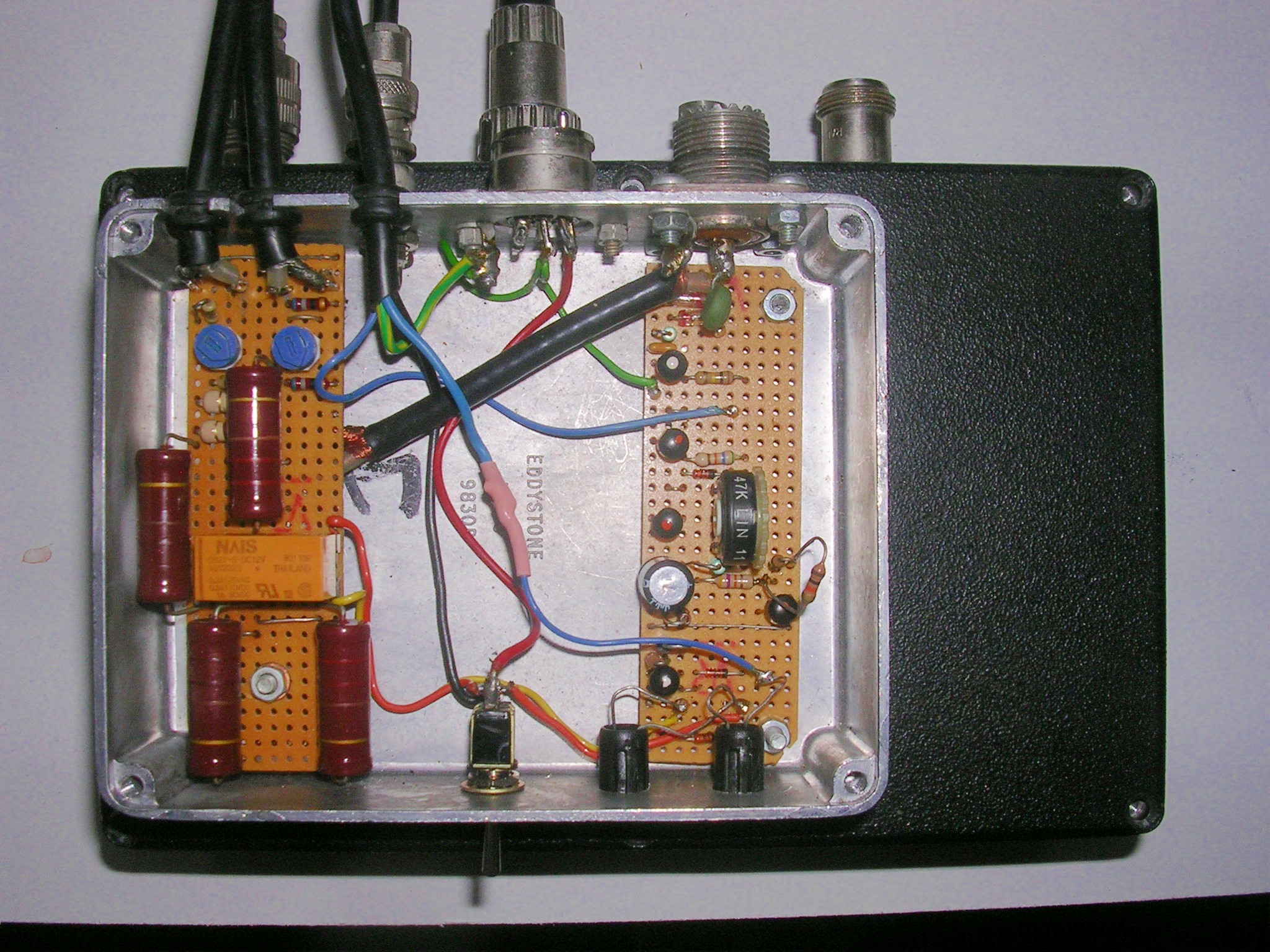
This is my contol box. The black cables link to the transverter underneath.
Short leads from the back of my control box go to the tranverter which has sockets for for Tx-UHF, Rx-BNC and Power-DIN. The 70cms output is N-type.
On the left is the change over relay, dummy load (for 10W input) and pots. to set levels. On the right is my 'fail safe' control circuit. With no power the Tx input goes to the dummy load, not the receive output. There is a delay adjustment pot (and an *SOT resistor hung next to it!). Change over is RF sensed but there is also a Phono socket that may act as, or be connected to, a PTT line. The HF in/out is a UHF socket and the power DIN. On the front of the box is a power 'on' switch (I don't need a big one, I only get about 5W output) and two LEDs, Green for Power 'On' and Red for 'TX'.
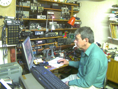
It sits, along with other transverters, on a high shelf. The green light is 'On'.
*SOT... In this context 'SOT' stands for 'Select On Test'. My original value didn't work out well and adding one chosen experimentally solved the problem. Like so many 'temporary' fixes, it has become permanent.

John Everingham. G4TRN, FTCL
Webmaster.
email:- g4trn(at)saundrecs.co.uk