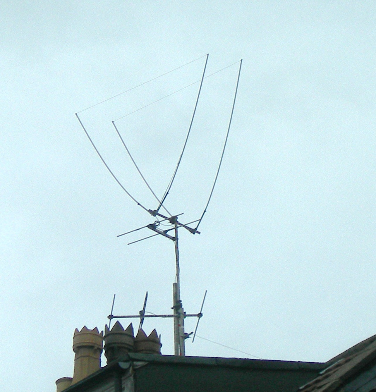
Tri-Band 'White Stick' Antenna Repair
Having just re-built my decades old two element (horizontally polarised) 6m delta loop...
I started wondering about a vertically polarised 6m antenna.
I used to have one, a ground plane that covered 6m and 2m. It worked well enough but disintegrated many years ago. Corrosion burst all the cast aluminium parts apart. It was then that I remembered a 10ft tall white stick antenna that had been standing in a corner ever since it arrived, ten or more years ago. Like many things to do with my amateur radio it had an unspecified problem and was left with me.
I enjoy sorting things out. Inside the fibre glass tube of these antennas is a thick wire conductor and various traps... coils and capacitors. There is not much to go wrong.
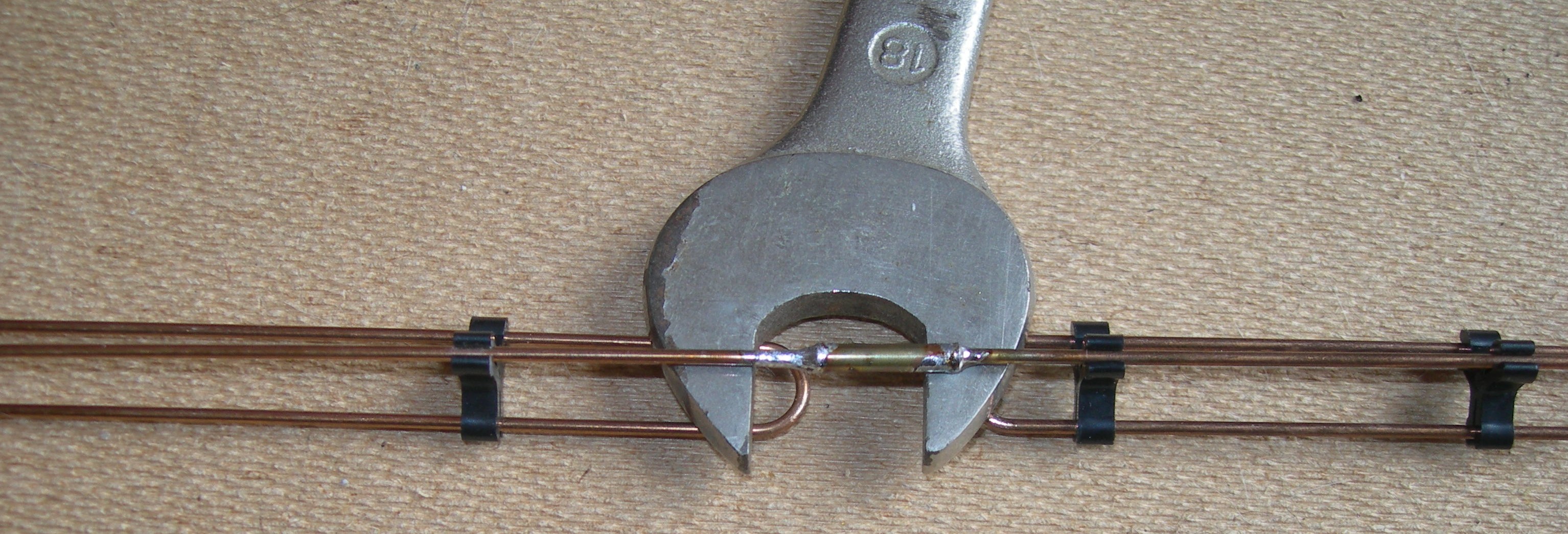
This one was in nice condition, having become unreliable fairly early in its life and it came apart very easily. The problem was at the join between two sections. A brass sleeve joined them and the solder had failed on one side. It had only been inserted about 3mm. When I came to solder it back I decided that this was too small an amount to be be reliable and wondered if it would be wise to shorten the antenna by pushing more into the sleeve. I tried and it would not go. It butted up against the other part. When I unsoldered the sleeve completely it was clear that the sleeve was in the wrong place and that the antenna conductors should butt up against each other half way along the sleeve.
I cleaned everything up and tried to reassemble the joint. Not so easy as it sounds. Perhaps I should have crimped the sleeve. In the event I used an open ended spanner to act as a weight to hold the antenna conductors in good alignment and at the same time act as a heat sink so that I could fix one joint at a time. The 18mm spanner will give you a good idea of the size. (The background is a sheet of hardboard.)
(Right click the image for a much larger view.)
You can see how far to the left the original joint sleeve was positioned. The break in the conductor is mid way between the single turn loops. The loops had to be aligned properly to enable them to fit into the tube. The next image shows more of the antenna and a board with two capacitors on it. The white blobs are simple foam plastic to steady the conductor assembly within the tube.

(Right click the image for a much larger view.)
A quick test indoors with my FT817 (yes... there is more than enough height in my living room to stand it up!) seems to demonstrate that it works properly now. The SWR is less than the rig will display, and I could hear repeaters on 70cms and carriers and other noises on 6m. 2m was end to end noise! The next step is to get it out onto the roof for a proper test, and then perhaps fix it in place of my present dual band white stick.
August update... Now it is out in the open my repair is confirmed. The antenna is working and exhibits low SWR. At first I was pleased by the lower noise it produced (you need to switch to SSB mode to check this). However, as most signals are down compared to my two band antenna, this may not be a good thing. The next step is to change the position of the antennas over so that the tribander gets the advantage of good VHF/UHF coax as well as the same site.
I have now found where the tribander came from... About fifteen years ago I swapped a good dual band antenna for it after it had failed for a friend during a particularly bad wind storm. It had become intermittent and presented a very unstable load. This came out during a contact this morning. The dual band antenna is still working, and, in a strange twist, the only station that has come in to me stronger on the tribander than on my dualbander, is that friend!
John Everingham. G4TRN
Webmaster.
email:- g4trn(at)saundrecs.co.uk
July/August 2020
Recoded for HTML5 June 2022.

