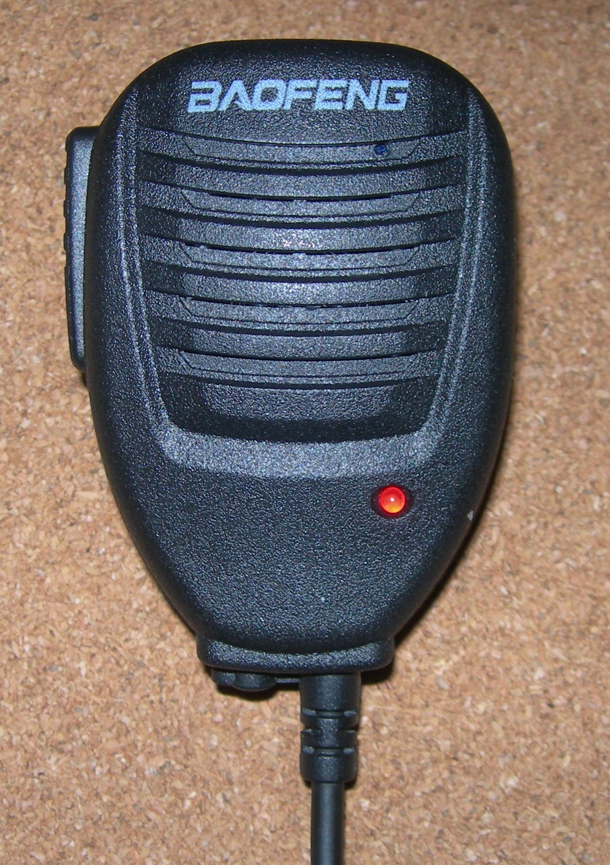
Baofeng Speaker Mic
Modification
I received very poor audio reports when using this microphone. After searching the web I found that the problem was universal and there were several fixes, depending on the actual version of speaker mic. I checked them out along with my own ideas. They all made a difference but none were as effective as I hoped.
Mechanical Issues
In my unit the electret element was hanging, by its connecting wires, in a cylindrical 'dock' that was far too big for it. Unlike many examples though, there was a small hole from the dock to the outside world.
If you do not have a hole you must make one, or move the microphone element so that it listens through a small hole.
Microphone elements seem to be 6.5mm or 9mm diameter. My dock was 7.5mm. and as I could not find a new mic to fit I added packing round it so that it was a tight push fit in the dock. The front of the mic must be isolated from the internal space that contains the loudspeaker.
The results of this restoration of the original designer's intention were disappointing. The tonal balance was all wrong and the sound was very coloured. 'Head in a bucket' is an apt description. Something else was going on.
Electrical Issues
Incorrectly fitted curly cord. This is a known condition, but not recognised as spoiling the audio. It does!
Audio level too high. This causes distorted TX audio and can be reduced by speaking more quietly, but it is well worth reducing it electronically.
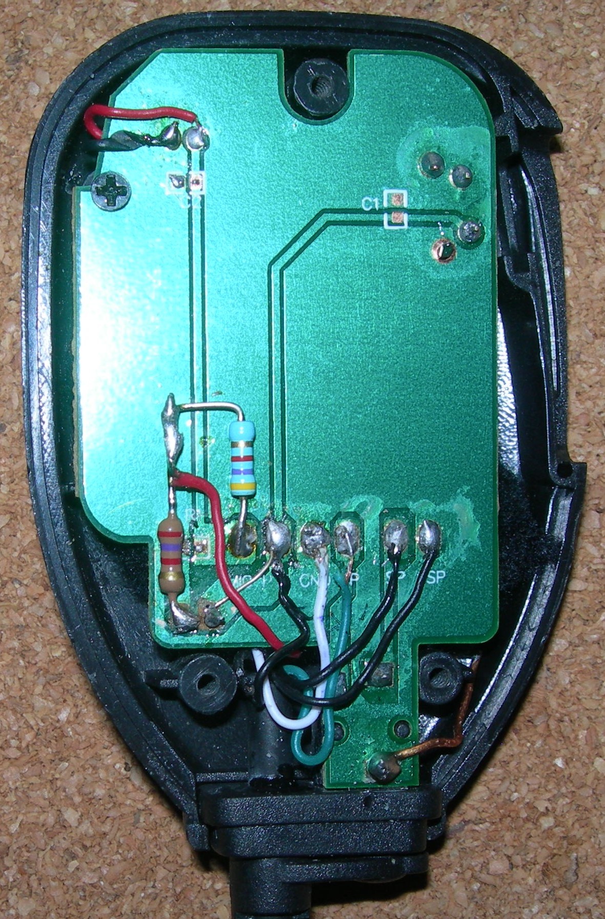
Here is a picture of my unit, after modification. There were also repairs needed because I damaged the board while hooking up test connections and configurations.
The six solder pads for the wire connections
are marked on the board, from left to right...
MIC PTT GND SP SP SP
(Right click the image for a much larger view.)
- Do not disturb the two black LS wires on the right. They simply connect to the speaker.
- Note the thick copper I wire added as a ground connection for a test meter at the bottom right.
- The pin connections for the plug, with typical curly cord wire colours, are:
| Board Marking | Function | Connection | Colour |
| MIC | TX Audio | Ring on big plug, | RED |
| PTT | Push to Talk | Sleeve on big plug, | BLACK |
| GND | Ground | Sleeve on small plug, | WHITE |
| SP | RX Audio | Tip on small plug, | GREEN |
Check that the wires in the curly cord connect to the expected plug contacts (above). If they do not, make your own connection table.
Make sure that the wires connect to the correct pads on the circuit board.
(I had to interchange the GREEN and WHITE wires. These are the usual culprits.)
When the GREEN and WHITE wires are the wrong way round the mic insert is grounded through the loudspeaker. This makes the speaker function as a second microphone, in series with the electret. The speaker favours low frequencies and is very resonant. No wonder the TX audio quality is strange!
The TX audio wire (RED) carries the DC supply to the speaker/mic TX LED as well as the audio. The current is limited by R1 ('222', 2K2) left of the MIC pad. I accidentally destroyed mine. It is no great loss. With it gone I replaced it (with 2K7, the nearest I had, no problem). This makes it easy to connect a resistor (mine is 4K7, selected on test) in series with the electret element. The junction of the two resistors and the RED wire is dressed away from the circuit board. There is plenty of room for 1/4W rsistors.
When testing note that if the speaker mic is plugged in, it is the speaker mic that functions when the TCR PTT is pressed (and the regular mic in the TCR is inactive). Also, because of the RF generated in TX mode, any nearby or connected analogue multimeter is likely to indicate a voltage, even a reverse voltage. (This is because of the protective diodes fitted in it.)
Take great care when moving the cicuit board. The LED track connections will break away with very little force and I broke mine. I have re-fitted the LED with supporting sleeving between the board and the LED and a wire link to the PTT pad.
The speaker/mic double plug follows the 'Kenwood' standard. (The alternative 'Icom' or 'Yaesu' system is different and works by connecting the ground side of the microphone to cicuit ground.) I usually use a parallel resistor to reduce the mic output. With my Baofeng this killed the TX LED. My first tests were made with the resistor in series with black wire to the mic element. There is plenty of circuit track available for a ground connection. There is no reason why this unorthodox configuration should not be employed and the original R1 left in place.
As a final step I have added layers of acrylic felt (from a craft shop) above and below the circuit board. This reduces the colouration produced by the small mylar loudspeaker and improves the sound of received signals.
John Everingham. G4TRN
Webmaster.
email:- g4trn(at)saundrecs.co.uk
June 2021
May 2025. Another example, on the right, image from G1DCG.
Externally it looks the same.
This one has no problems.
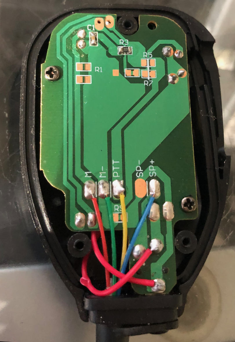
(Both images my be enlarged by right clicking.)
Stereo Headset Adapter
for
Baofeng UV5-R etc
Problems and Solutions
I have just (May 2025) purchased an adapter lead that is marketed to enable the user of a UV5‑R 'walkie-talkie' to listen with stereo headphones or earbuds. This product is unbranded.
I have seen others, or, at any rate, others with a different image. I suspect that the devil is in the fine detail and they may work properly with other radios that share the same 'Kenwood' plug cofiguration, but not Baofeng and its ilk.
 There are problems with this device.
The audio is heard, but the earpieces are out of phase.
The PTT does work, but no audio is transmitted.
Actually some audio may be transmitted... the right hand earpiece acts as a microphone!
There are several ways of sorting this issue out. They all involve wire cutting and soldering. For me, the first choice was to diagnose and correct the problem with the supplied device. (There are easier ways, but I have masochistic tendencies so I will describe them later.)
The first step was to identify the nature of the 3.5mm. headphone socket. It is the usual 3 connector variety. I was half hoping that it would be 4 connector. If it had been then full audo transmit as well as receive using a phone earbud set with a microphone should be possible.
The next step was to draw up a connection table. The problem could be related to the mistakes with my speaker/mic described above. There are three wires. Check that yours are connected the same way. Make your own connection table if they are not. The wire colours may not be the same.
| 3.5mm Socket | Wire Colour | Connection | Action |
| Tip | White | Left Audio | Keep (rejoin if cut) |
| Ring | Black | Right Audio | Cut and Splice to White Wire from Plug. |
| Sleeve | Red | Common | Cut and Connect to (cut) Black Wire from Plug. |
| 2.5mm Plug | Wire Colour | Connection | Action |
| Tip | White | Audio (mono) | Keep and Splice in Black Wire from socket. |
| Ring | NC | - | - |
| Sleeve | Black | Ground | Cut and connect to (cut) Red Wire from Socket. |
| 3.5mm Plug | Wire Colour | Connection | Action |
| Tip | NC | - | - |
| Ring | Red | TX function (not used) | Cut and Connect Socket side to White Wire. |
| Sleeve | NC | - | - |
This is what has to be done...
- The red wire connection at the plug is not used and is cut.The socket connection is used.
- The black wire, ground, from the plug, is cut. Both ends are reconnected.
Work from the socket end. It is easiest to cut the cable and re-join the white wire at the junction with the black wire from the socket. There are three wires, but only two connecting points. Only two wires from the plug are used. The junction between the cut cable sections can be either way round but I prefer to use ground for common signal returns. Nobody sees the wire colours, which are at variance with standard usage.
- The 3.5mm socket tip (left, white) is connected, to the ring (right, black). They are then connected to the white wire (mono) audio from the 2.5mm plug tip. This parallel connection corrects the previous out of phase series connection.
- The sleeve (red) of the 3.5mm socket is connected to the common connection, sleeve (black, ground) connection from the 2.5mm plug
- Check your connections as you go. You need to make sure that you have correctly identified the common connection for the headset. I prefer to use an analogue multimeter with a pointer. On the R x 1 Ohms range it passes enough current through earpieces to make a clear click. Clip one lead of your test meter to it and then touch the other on each of the other connections before you solder them together. When you are right you will be able to produce a left or right click at will.
You don't need to note which is which because they will be joined together. The click will then be on both sides at the same time and will sound 'in your head'. If you note the resistance readings, low readings are for a single earpiece (they should both be the same) and a higher reading (double the low one) indicates that the earpieces are connected in series.
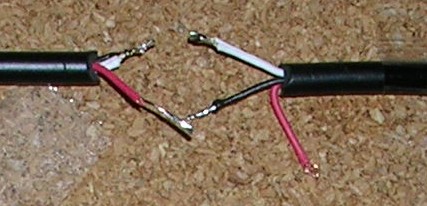
Headset lead on the left ----- Plug lead on the right.
There is nothing wrong with series connection, except that with three wire stereo you cannot adjust the phase, which should be correct for parallel connection and will be wrong for series connection if it is. The sound effect is not pleasant and can be very unpleasant with low pitched sounds. (You can get away with it for communications purposes, but it is well worth avoiding. It could 'Do yer edd in.'.)
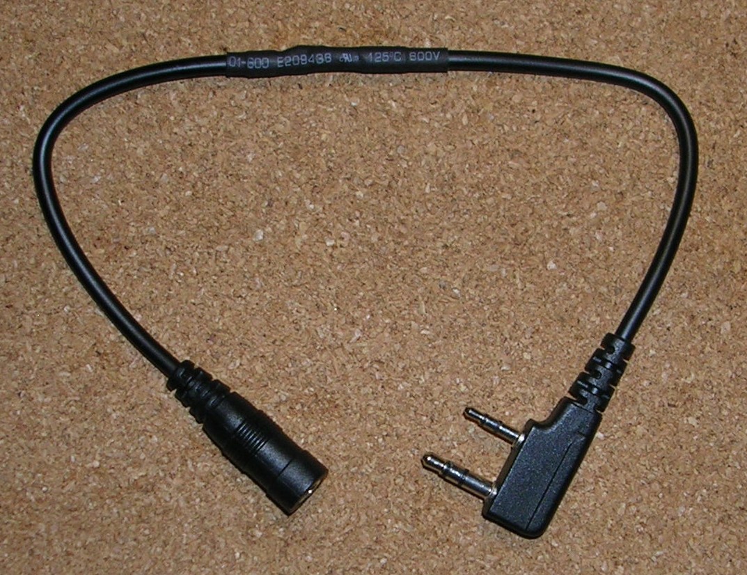
The PTT works normally, with transmit audio from the TCR microphone. .
You really need a right angle 2.5mm plug. The one advantage of modifying this adapter to make it work acceptably is the ready moulded plug. Be careful how you use it. It is easy to forget the socket cover and tear it off when pulling the plug out. Other ways of making a stereo headset work for this radio include...
- Cut the 3.5mm socket off the orignal adapter and rewire it as above. Easy, and neat. (I didn't have a 3.5mm line socket available. Not easy to get any more. No Maplin or equivalent store in town.)
- Buy a ready made adapter lead with a 2.5mm to 3.5mm stereo with a right angle 2.5mm plug. Readily available and inexpensive, from Kenable. You will have to devise your own way of converting from mono to stereo and will probably end up cutting the socket off and fitting a new one. A good and neat solution. The right angle 2.5mm plug will help preserve your Baofeng socket cover.
- Use a 2.5mm to 3.5mm adapter. The disadvantage is the amount of space it takes up and the damage that could be caused to the TCR by daisy chained adapters. You still have to convert the mono feed to stereo.
- Hard wire your own 2.5mm plug to a 3.5mm stereo socket. The easy way to do this is to buy a ready made 3.5mm extension lead and replace the plug. This is a good way to go if you can find a 2.5mm right angle plug.
There is room for experiment with a phone headset. The ring connection to the 3.5mm plug may be usable in conjunction with the fourth contact of a phone headset (the one at the base of the plug) for audio transmission. (The third connection, the second ring, is ground.)
The standard trick for making stereo feeds compatible with mono plugs is to insert equal value series resistors into each stereo socket connection (Left and Right) that may be accessed by a mono plug. (50R is a typical value.) By doing this the spare channel (Right) when shorted by the mono plug sleeve, will not silence the remaining (Left) channel. There will be a loss of volume, but this can usually be remedied by the adjustment of a level or volume control.
