Fitting an Amplifying Stage into an HM-103.
I have brought my IC-706MkII out of retirement for use as a 'natter box' in a 'second shack', study/bedroom. For this application I prefer to use a hand mic and the inadequacy of the rig's amplification irked me again. I wanted good FM performance as well SSB. I am using it on 2m and transverting from HF around 10m to 70cms using my old MM432-28 S transverter.
The microphone element has two connections (three connections according to the user's manual) and is connected to the rig with a simple single screened conductor in the curly cord. Power is fed down the audio line and the electret element (which includes an FET) is configured as a source follower. The schematic for the microphone supplied with the IC-706MkIIG seems to apply to most earlier (if nor all!) IC-706 models.
An internet search produced a similar circuit to the one I was considering but the method of connection was not clear and the build instructions advised removing all the original circuitry. From I3MDU This idea did nor appeal to me and I decided to 'roll my own'. The knowledge that this was a 'trodden path' was ecouraging, but I wanted a less radical and non-destructive solution.
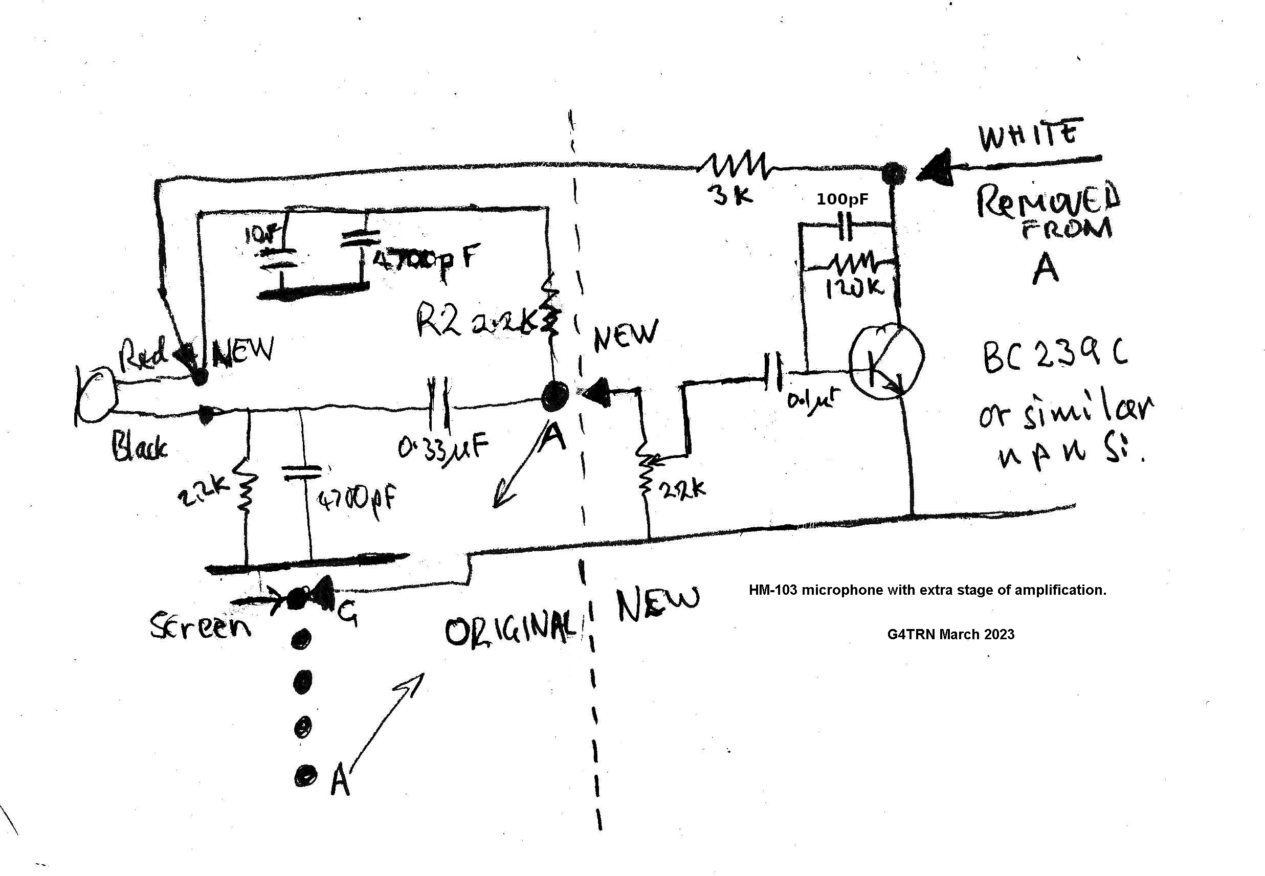
The left hand part of the circuit below is the original.
The right hand is my addition.

See the text concerning R2. (It may be best to remove it. I have.)
(Right click the image for a much larger view.)
The audio signal from the electret element appears at Pin A. The white wire from the curly cord is unsoldered from Pin A and taken to a simple common emitter transitor amplifier. (There is no collector load or DC blocking capacitor because they are in the rig.) Pin A is connected to a (linear) preset potentiometer the slider of which goes to the base of the new amplifying stage. The collector of the amplifier is connected to the de-coupling capacitors of the original circuit via a replacement resistor. This enables DC to be provided direct to the positive connection on the electret element without any audio feed back. There are the usual RF decoupling and DC blocking capacitors.
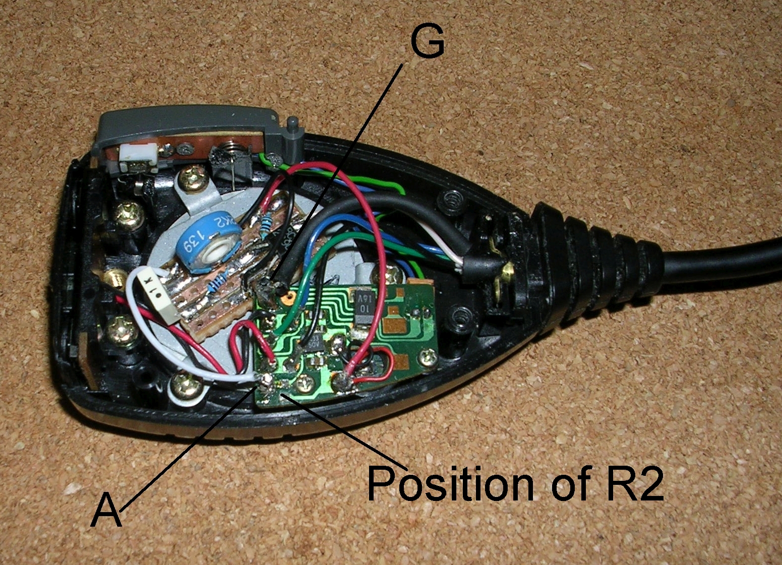
There is ample room for standard components. I mounted mine on a piece of strip board. The tracks are uppermost because I wanted to be able to test and change components. There is thick double sided sticky foam under the strip board and the thick copper connection between the ground track and Pin G holds it in place.
June 2025... following RF feedback issues on 80m I added a 100pf capacitor across the bias resistor. (The circuit diagram has been digitally modified to include this, but it does not show in the image yet.)

(Right click the image for a much larger view.)
Somewhere along the line I lost R2. It probably disappeared up my solder sucker. It's position is clearly marked on the image file. I had decided to leave it in place and accept the attentuation it would cause. My intial experiments confirmed that this was a viable decision. When I was ready to test again I unexpectedly found I had a lot more gain. It was a mistake not to stop and find out exactly why. I now think it was the result of removing R2. I didn't see that it was gone until I looked at the enlarged image! My hand is not steady and I have had this sort of run in with surface mount components before.
The 706 did not like the very high gain and imposed heavy compression. The menu driven MIC GAIN function worked but it proved to be impossible to get acceptable audio quality, even at low deviation levels. A gain control in the mic was essential. I have now set it at about 1/4 way up. With R2 in place you may be able to dispense with the preset resistor gain control. If you decide to leave R2 and have a gain control then the top of the gain control can be connected to the black wire connection to the electret elenent and the use of another capacitor avoided. (I prefer not to use ceramic capacitors for audio.)
If you attempt this modification be very careful with your hot soldering iron. You can see where I slipped and damaged the PTT spring pillar. The PTT wires were retained by melted plastic as part of the original assembly! Dress the connecting wires away from the top cover fixing screw. There is very little clearance. I have reset the presets in the rig to the handbook values for SSB. Everything is working well.
John Everingham. G4TRN, FTCL
Webmaster.
email:- g4trn(at)saundrecs.co.uk