Base Mic... Home Brew.
I very soon found the need for a 'base mic' with locking PTT switch for my radio transceivers. Although I enjoy twiddling knobs, and developed 'safe cracker's fingers' coaxing the best from regenerative receivers in my youth, my soldering iron was usually 'on' and I needed both hands free to keep happy. A 'fist' mic was too restricting.

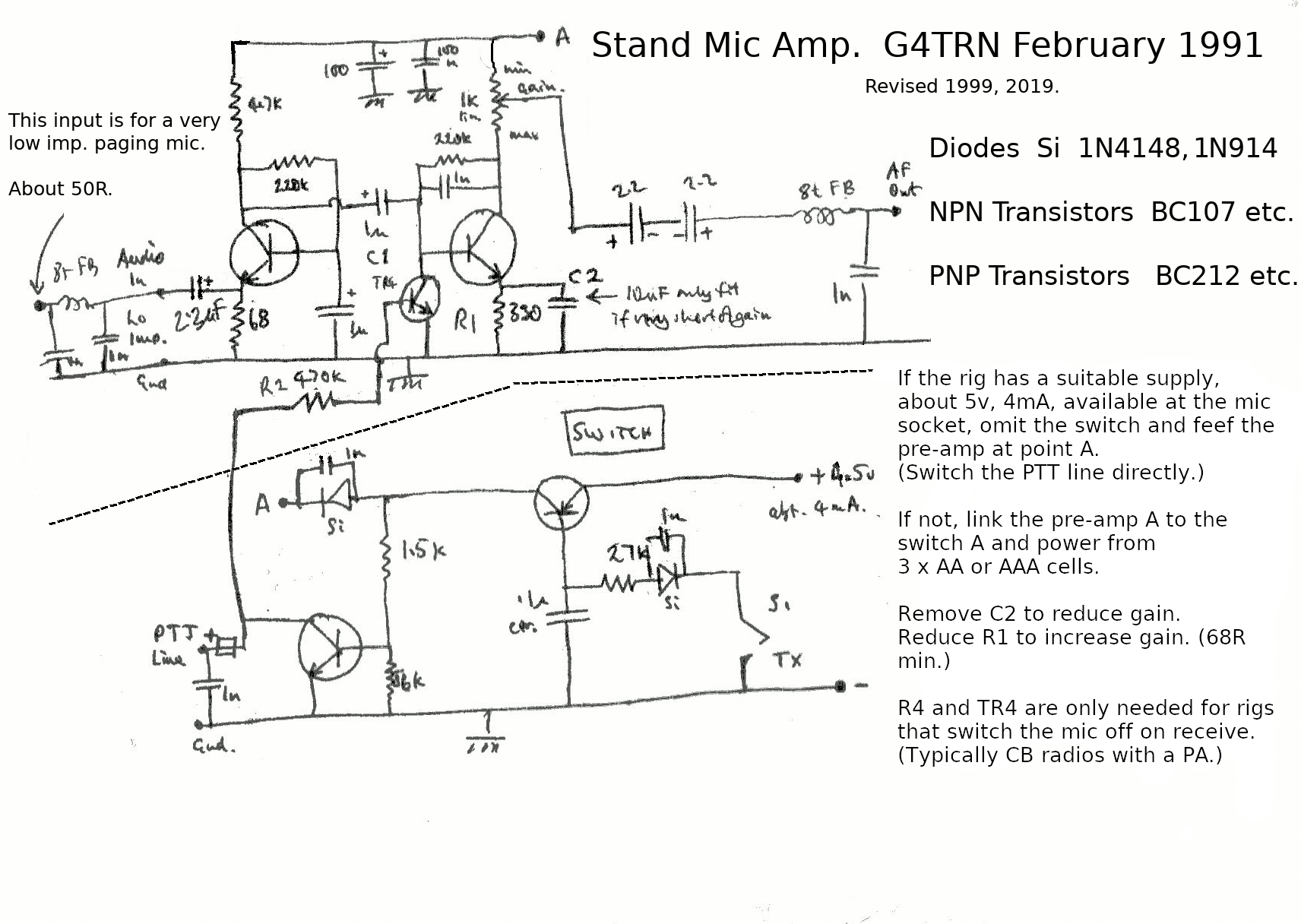
(Right click the image for a much larger view.)
My first mic was designed to be 'universal' and capable of being plugged into any rig. I use DIN connectors, but there are drawbacks. Their contacts are not gold plated and are not as reliable as I would like. From time to time I unplug and re-plug them. To produce a latching PTT I use two push switches in parallel, on 'Push On' and then 'Push Off', the other Push to close ('momentary'). The latest addition has been another 'Push On' and then 'Push Off' switch in parallel with the PTT line. This enables transmission without an active microphone. Using this I am able to feed in data, or audio, from a computer (via an isolating transformer). The circuit, like Topsy, grew.
The first step was to work out how to utilise a very low impedance goose neck mic bought cheaply at a rally. I used a grounded base input circuit. At the time I thought this was an inventive idea, but it now comes up very quickly on Google. I powered the amplifier with three AA cells. All went well, but they went flat very quickly! When the rig was powered down it switched the amplifier on... I added a switching stage. Then, with an early CB radio I ran into problems at the change from Tx to Rx as the amplifier continued to function and feed back resulted... I added a 'mute' function.
I was rather short of gain for the IC706 MkII and employed both options to enable satifactory working. (Check out my pdf on the subject... IC706 TX Audio setting (pdf).) Now that I am using an FT897D I'm back on the original configuration.
The resulting circuit diagram reflects the development. The image is a scan of my 1991 scribble, tidied up with digital manipulation in 2019. How things change! And there is a typo in the added image text. More work needed. There may be a pdf later, but I'm having trouble getting it to print to an A4 pdf page properly at the moment
Here is a pdf of the image file circuit (within the box above). It will print full page, landscape. I have left the typo!
John Everingham. G4TRN, FTCL
Webmaster.
email:- g4trn(at)saundrecs.co.uk