A Cautionary Tale..
First written in July 2024, updated in June 2025. Do check it out!
Over the past week I have been enjoying myself putting together a kit project. The Yoofab Magnetic Loop antenna. More about that later when I have powered it up and tried it out.
The circuit board is not the usual style, with holes for component leads. Standard parts are connected to pads, surface mount style. This is a favourite method for experimenters, quick and easily modified. All went well until I came to the transistors. I don't trust myself to remember pinouts so I looked in the instruction manual for the usual pinout diagram.
There is no transistor connection diagram but the board is clearly marked with the transistor outline (TO92, a circle with a flat section) with E, B and C for the lead pads. At times like this I remember Morecambe and Wise... "All the right notes, not necessarily in the right order." and I feel the need to double check. The three connection wires in a straight line have to be bent to match solder pads set out as three corners of a square. This is not a problem in any way, there is plenty of space and no leads are crossed. However, I wanted confirmation in the form a diagram with the connections identified in order as they came out of the transistor. I was reaching for my "Towers' International Transistor Selector" (Revised Edition, Update 2, 1980 £9.50) data book, when I remembered that this is the twenty first century and my PC was running.
All I needed to do was open my browser and key 2N3904 into Google.
BIG MISTAKE!
The first info I remember seeing about the Yoofab loop listed 2N2222 transistors so I selected a page that promised an analysis of the difference between these and the 2N3904 transistors in the kit. For most purposes the 2N3904 and 2N2222 are interchangeable (and they have the same pinout).
BIG MISTAKE!
I spent the next half hour trying to reconcile the image on my screen with the markings on the circuit board. Eventually I saw the light and looked at a manufacturer's 2N3904 data sheet. Revelation! The hobbyist page I had selected was wrong. The Collector and Emitter connections had been transposed.
MORAL
Do not trust everything you see on a computer screen. The information on screens does not have the authority of the stone tablets Moses brought down Mount Sinai.
CORRECT CONNECTIONS
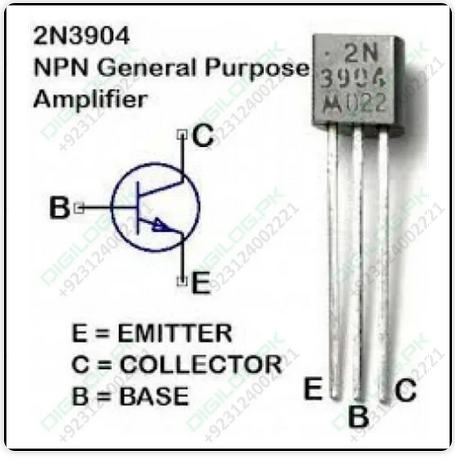
Here is the correct pinout. Most pinout diagrams include a numbered schematic.
Numbering is useful when there are many connections. However, it implies order and great care has to be exercised regarding top and bottom views. If you play with integrated circuits and valves you will know what I mean. (I grew up with valves (tubes). The transistor may be the fasted fuse on three legs. A battery powered triode is the fastest fuse on four legs.)
I found this pinout on the web at
https://digilog.pk/products/2n3904-3904-npn-transistor

I think this presentation of the basic information is ideal. It avoids numbering and with it the possibility of contradiction and misunderstanding. I commend this site to anyone who reads this.
PROBLEM PAGE
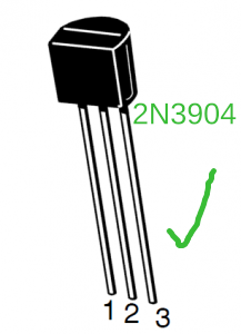
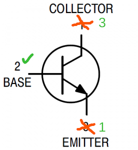
These images have been copied from
https://www.diyengineers.com/2022/04/14/2n3904-vs-2n2222/
(The red and green additions to the images are mine.)


THE ORIGINAL INFORMATION IS WRONG for the 2N3904.
Schematics usually follow the convention of the collector at the top.
Here, the collector should be numbered 3 and the emitter 1.
The url above can be copied to a browser. it is not a hyperlink.
My guess was that the information was copied incorrectly from Wikipedia.
https://en.wikipedia.org/wiki/2N3904The information there is correct but presented in a non-standard way.
The transistor is depicted 'flat down', from below. and the diagram is 'Top view".
The warning regarding the diagram must be heeded.
Perhaps Wikipedia felt it was necessary to adopt a unique presentation in order to discourage copying. If so, I understand, but this is the wrong way to do it. Look for yourself and consider the logic behind depicting things that cannot be seen directly. This presentation is very confusing
For myself, my paper schematic ideas for my projects include pinout diagrams of the devices I intend use. The Towers' book must have been my model...
.png) |
This is everything I need to know when I connect transistors to a circuit board... The lead wires can be seen. |
FOLLOW UP
I used the comments box attached to the web page to report the error two weeks ago. I am still awaiting the attention of the site moderator. Nothing has been done and I have not been contacted. I have just used their standard contact form to advise them of this page's error and receoved an automated reply.
Nearly a year later, in June 2025, I had an urge to see if anything had been changed on the diyengineers web page. The dodgy information is still centre stage. I re-read the whole page and followed the attribution the the source of the information.
https://www.onsemi.com/pdf/datasheet/p2n2222a-d.pdfI now think it is the result of not appreciating the fine detail of the Onsemi data sheet for their P2N2222A. It is electrically similar to, but not physically the same as the 2N3904
This pdf shows the same information. Note the 'STYLE 17' in the transistor details on Page 1. You can decode this on Page 7. The 'Devil is in the Detail'. Note the identifier for the device in question. It is on the data sheet and in the data sheet url, but it has not made its way onto the diyengineers site. It is a P2N2222A The 'A' could, but doesn't, concern us. The 'P' does. (The usual pin out for the 2N2222 transistor is 'STYLE 1'.)
BAD MISTAKE. But something we can all learn from.
A bit more Googling and I found that I am certainly not the only one who has been caught by this contradiction. The same illustrations and the same manufacturer.
https://electronics.stackexchange.com/questions/109391/2n2222a-mismatch-between-emitter-and-collectorRead the entire thread.
The Yoofab Loop works well but may not be the answer to the my local noise level. Surprisingly, it enables previously impossible reception of the BBC on 198kHz by my Yaesu FT-897D. It also works for the Band II FM broadcast band. I can connect it to my wide band Yupitero scanner and get good reception on all bands without the inconvenience of a whip antenna.
John Everingham. G4TRN, FTCLWebmaster.
email:- g4trn(at)saundrecs.co.uk
TOP of SITE