G4TRN
UK Amateur Radio Station
My Low Voltage (13.8V) 25A PSU
These HiRes images are rendered small, to fit the page,
and will open to fill the screen if you wish.
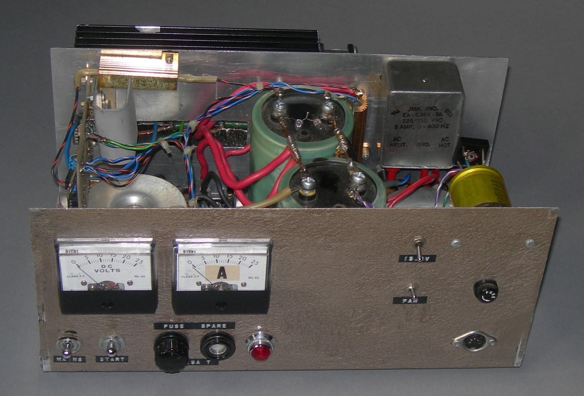
General view, cover off.
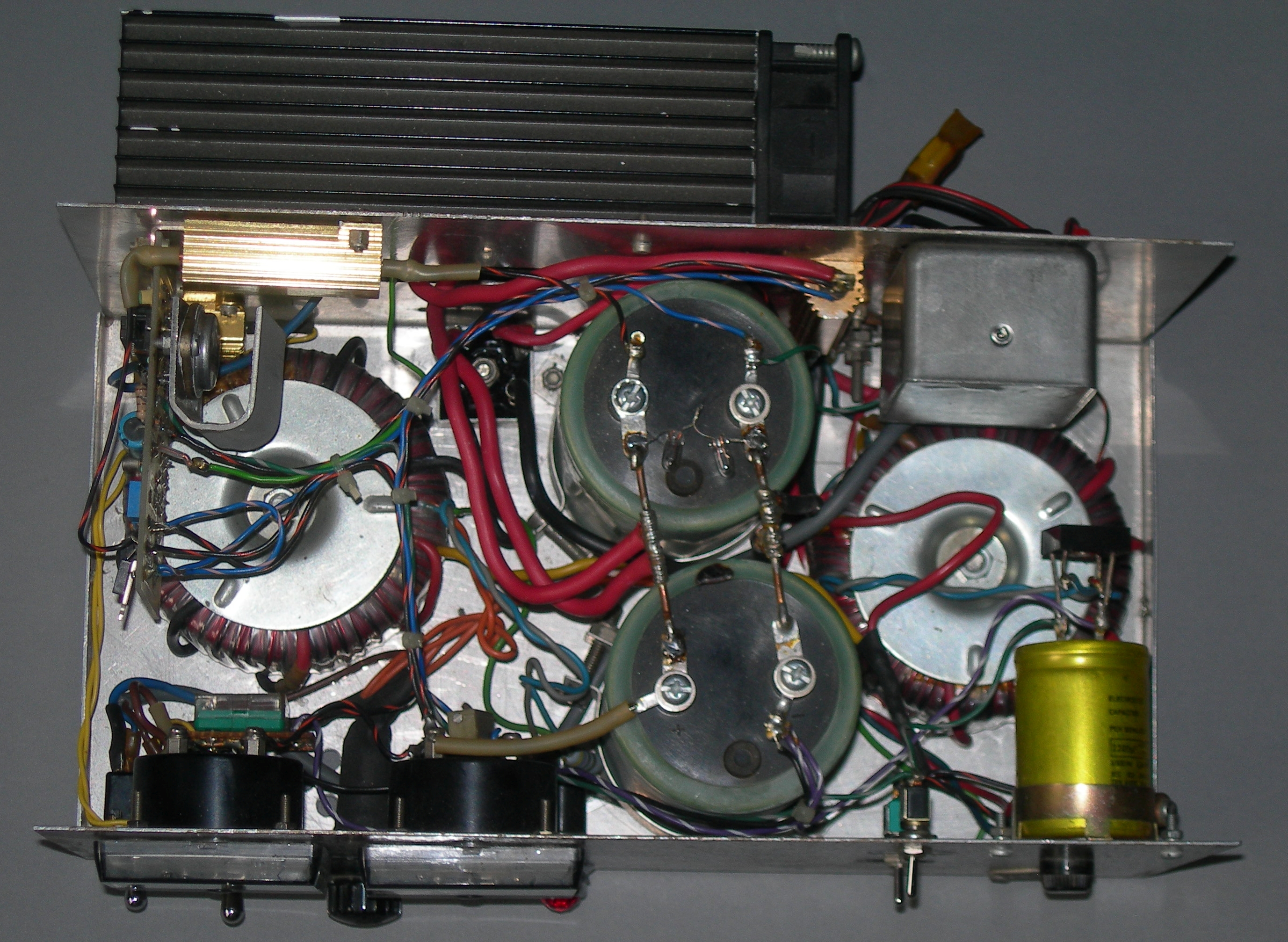
Plan view showing toroidal mains transformers,
very large reservoir capacitors
and (yellow) driver reservoir capacitor and rectifier.
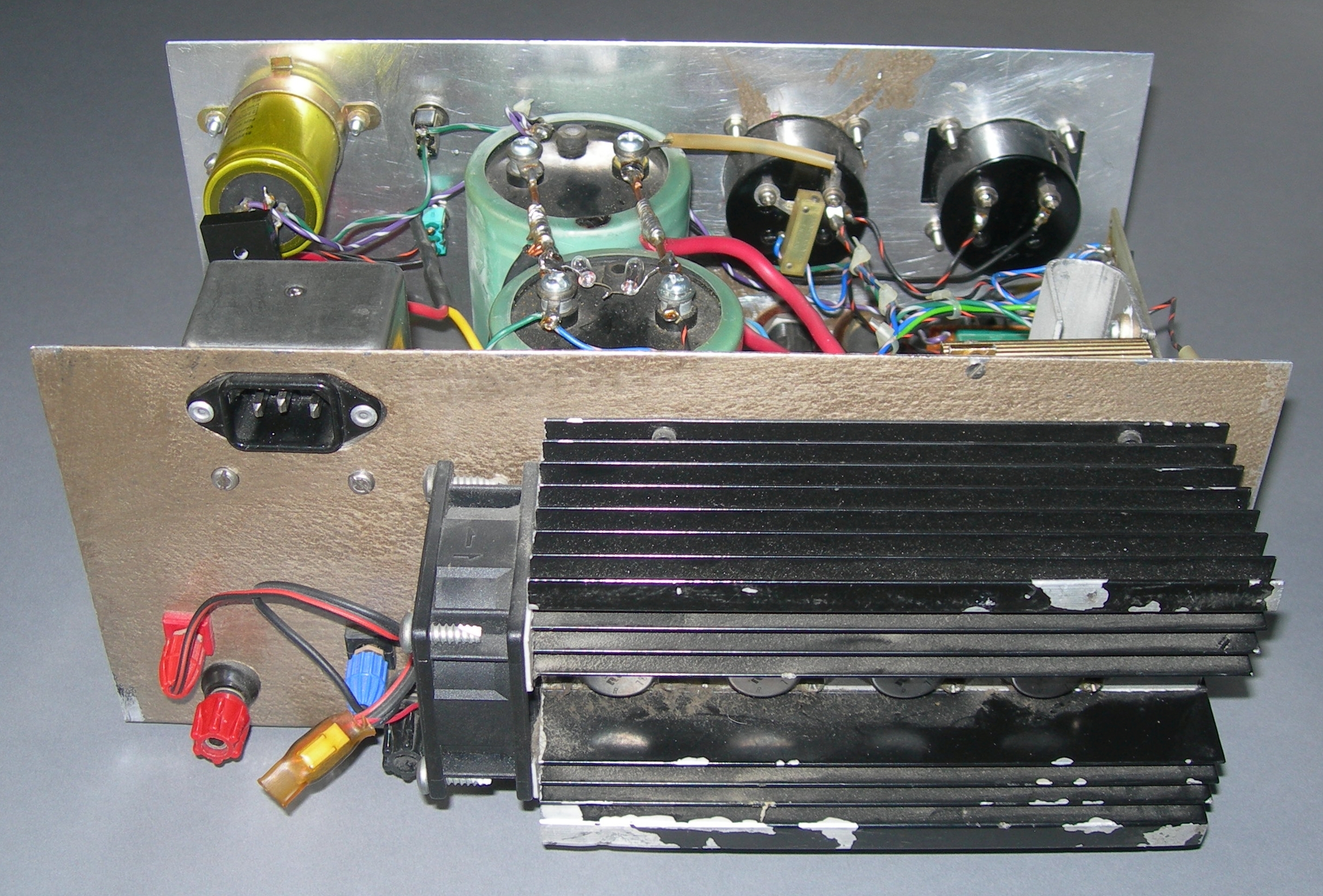
Rear view showing the battered heat sink
with 4 x 2N3055 pass transitors (from a rally junk sale).
I made this psu from collected odds and ends acquired at low price from rallies. The basis is the PW Marchwood design from June 1983. (Link to PDF print.) Switch mode low voltage power supplies were rare at the time and the surplus market was a good source of parts from, or originally intended for, the expanding computer market. The IEC connector needed to fit the mains filter was a novelty... there wasn't even one on the kitchen kettle! The case was from a failed psu project by a friend (note the original rectangular meter hole!). There are several unusual features...
1) Two toroidal transformers, primaries in parallel, main secondaries in series. Each has a low current secondary in addition to the high current one. These were very cheap at a rally. The high current secondaries are not quite high enough voltage so there is an extra 8 turns or so of insulated wire added to each. (Easy with a toroid.)
2) The reference and drive voltage for the pass transistors (4 x 2N3055) is derived from one of the low current secondaries and feeds the LM723 regulator on the basic voltage controller. This is a useful system that I have used in other supplies. The main regulator only needs to remove ripple, because its driver does not have to deal with the high ripple on the main reservoir capacitor the voltage level can be lower and the dissipation is lower as a result. One can utilise a lower voltage transformer and the whole thing is intrinsically safer for the attached units. The tiny '13.8v' switch controls the 25A output, but only passes the few hundreds of milliamps driving the pass transistors. From time to time I flick it off to see if there is any leakage. The other spare winding drives the panel lamp.
3) The SCR 'crowbar' protection circuit does not short the reservoir capacitors directly, but through a low value resistor. This resistor also feeds a 12v relay whose (normally 'off') contacts are in series with the 'live' mains feed (from an RF filter).
4) The panel power switch enables, or stops, but will not start the psu. The second switch is for 'soft start' and is momentary, push to make. This switch is in series with a resistor across the mains relay contacts. If all is well and there is no heavy load on the output, the relay closes after about one second and everything runs normally.
5) There are two 12v low current bulbs hung in series across the reservoir capacitors. These take very little current in normal operation and produce very little heat but they discharge the capacitor rather quickly when the power is cut and glow nicely as a warning when it is running.
There is no dedicated ammeter shunt. The indicator is essentially a millivoltmeter reading the drop across part of the internal circuitry.
In the event of an over voltage fault, the output of the psu is discharged very rapidly and it is switched off. Over current will also switch it off. The psu cannot be restarted until the fault is cleared.
I think I've been running this psu for 30 years with no problems apart from an intermittently dodgy drive transistor, replaced by a 2N3055 ten years ago. Nothing has suffered and, unlike many so called protection circuits, the psu itself suffers no damage from a trigger event.
On 11th. October 2015, after a session of news reading, the main fuse blew and all my 13.8v units shut down. My 2m qso continued (at 10W rather than 100W) because my trusty old (ancient!) TS700 runs directly from the mains. It was time to do some serious fault finding.
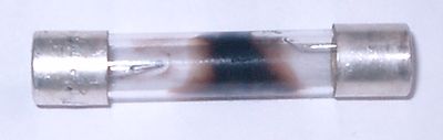
After cooling down, the psu struggled to start with my spare fuse, but was obviously in trouble. (Interesting smell, but no smoke!) The voltmeter crept up to 5v if I held the start switch down and the series resistor got rather hot.
When I disconnected the high current bridge rectifier everything perked up and looked better. A spare rectifier proved the point. It was only 25A so I did a search on the Maplin site and found a 35A rectifier (Maplin AR87U) for £2.49. There was a Maplin store within walking distance and a new bridge rectifier was in place within a couple of hours. All is working again... without plugging in my soldering iron! (The original rectifier was also a 35A type, they don't come easily at higher currents.)
Because I am reluctant to replace a failed component without trying to make sure it's replacement doesn't fail I have added a 'penny' washer below the head of the rectifier fixing bolt. If it has any effect at all it will improve the thermal contact between the rectifier and the chassis, and that may make a difference. Not that I will notice it if it lasts another 30 years!
Update!
On 8th. April 2018, in similar circumstances, the replacement rectifier failed. This time I have fitted a GBPC5010, 50A 1000V, from RS. I ordered two, the spare is tucked away inside the PSU for emergency use. I hope it may protect the one fitted in the same way that carrying an umbrella stops rain from falling.
The cause of the second failure remains a mystery, but as the rectifier specification was the same as the original it was not entirely unexpected. I did discover though that the IEC plug on the mains connecting lead did not mate well with its socket. The inbuilt receptacles seemed too short and contact was only made when the plug was rammed in the last fraction of a millimetre. Perhaps it had been dislodged momentarily and caused a surge. (I have replaced the lead with one that gives a small but appreciable of amount of sliding contact when plugged in.) Whilst locating a higher spec. rectifier I browsed several data sheets and discovered that for a capacitive load the current rating should be reduced by 50%. Perhaps these two issues combined to kill the first two rectifiers.
More...
On 20th. May 2018, after a session of 100W (Peaks over 20 Amps) SSB on 80m. and a fairly steady 5 Amp drain for 45 mins. afterwards, about 15 minutes into my 2m reading (steady 14 Amp drain for FM) it tripped again. This time though all I had to do was shut down all the loads and restart. SUCCESS! I was able to continue at high power. I'm beginning to wonder if there is something coming up the mains at around 11:15 local.
More... and More...
I've had a few more non-destructive trips, all at the same time, and I think I have found the answer.
We have an old chest freezer that runs rather too cold. Back in the Spring it struck me that there was so much latency in its workings that I could regulate it with a cheap time switch. I bought one for a lot less than a fiver and set it to switch off at 15 minutes to the hour, and back on again on the hour. Since I changed the settings so as to avoid a switch off between 10.30am and 11.00am I have had no more trouble.
I've just had another thought... Perhaps I've been lucky for the last two weeks! I'd better check the settings again... It is still on BST.
At any rate, I think I'm winning with the power bill. £20.00 less than usual for the first quarter with the time switch in circuit.
John Everingham. G4TRN, FTCLWebmaster.
email:- g4trn(at)saundrecs.co.uk
TOP of SITE